Repository navigation
ESP32 PWM #7806
Description

It would be nice to have the full 16 bit resolution available for the duty cycle. In my use case I am controlling a digital servo with it. I didn't want to have to add a PWM IC to the boards I am building because there would be added expense to have the PWM IC soldered onto the boards. The IC's are SMDs with some pretty small pins and doing it by hand would result in a high failure rate if I even managed to get any soldered down properly at all.
One such PWM IC is the PCA9685 and it has a 12 bit duty resolution. This allows me to turn a servo from 0° to 359° using 0.0879° increments. With the EP32 being locked to a 10 bit resolution my increments would become 0.3516° increment which is quite a large difference. if the full 16 bits were available the increments would become 0.0055° if the servo is capable of moving that small an amount. I know the ones that I am using work with 12 bit.
Adding a function or property that would allow a user to obtain what the max duty cycle is would be extremely handy to have. max_duty = (2 ** timer_cfg.duty_resolution) - 1
It would also be nice to have an additional parameter added to the set frequency and the constructor that would allow a user to set a lower duty resolution. If the parameter is not supplied then the maximum duty resolution would be used. it would be simple to add in a check to ensure that a provided duty resolution was not higher then the maximum if it is then raise an exception.
Now I am not sure if anyone has worked with a high quality digital servo at all. These things are capable of moving 60° in 0.2 seconds and sometimes faster. Without having the ledc_set_fade_with_step, ledc_set_fade_with_time functions exposed in some manner it becomes quite the task to throttle how fast the servo moves. Writing the code to handle that in Python does consume quite a bit of resources where I am sure using that functions would be considerably less.
I do not know how the threads work with the ESP32 and if they are "real" threads. If they are it would be helpful to also have the thread safe versions of the functions exposed or have the program automatically use a thread safe version if making a setting change that is not happening from the main thread. I would think there is a way to identify a main thread. I do not know if the non thread safe versions of functions are blocking calls or not. I would imagine the non thread safe fade functions would block until the fade completes.
The ESP32 has a whole bunch of PWM capabilities that are not exposed and it would be handy if they were. From reading the SDK and looking at the ESP32 port files I don't believe it would be hard to add the above mentioned things for someone that has worked with the backend MicroPython code. I would be willing to add the features is someone would explain how the MP_ROM_QSTR function/macro works and where the values that are passed to it is located.
Activity
wangshujun-tj commentedon Sep 21, 2021
The maximum accuracy of LEDC is only 14 bits. MPY currently uses 10 bits, and LEDC is still a little limited for this application. However, as long as the 14 bit accuracy is turned on, it is enough for steering gear control
Mcpwm is a module more suitable for realizing general PWM, and the disclosure of this information is fairly good
In the forum, I presented an example of using RMT module to realize steering gear drive, which can realize high-precision steering gear control without modifying firmware, and the setting is a little troublesome
dpgeorge commentedon Sep 21, 2021
ESP32 was improved in 52636fa. I'm not sure how much of the above has been addressed in that commit.
kdschlosser commentedon Sep 21, 2021
None of the things mentioned above are in that PR. It is good that it has been fixed for proper use of timers as this is going to be really helpful to me. I didn't study the code enough to notice that there was an issue with the timers.
I did find out that the fade functions cannot be stopped once they are started, this is not helpful at all and not having the ability to stop it if it is running is not useful. It will block a call made to change the duty until the fade has finished.
I went in and changed
#define PWRES (LEDC_TIMER_10_BIT)to#define PWRES (LEDC_TIMER_16_BIT)So the full duty resolution of 0-65535 would be available for a 50hz frequency instead of 0-1023 which is what a 10 bit resolution would give vs a 16 bit one. The ESP32 can handle 16 bit resolutions where the ESP8266 is limited to 10 bit I believe.Because of the large number of differences between hardware trying to make interfacing that hardware portable between different devices causes limitation to get put into place. So if a device has a lot more function then another in order to keep portability the code that has to be written would end up being for the lesser device. So a person that purchased a device say in this example because they want to have a higher PWM resolution is not going to be able to get the benefits because of a limitation in how the MicroPython code has been written.
Perhaps having a builtin attribute in MicroPython that can be used to identify the hardware that MicroPython has been compiled for would be a better solution. This way a user can write code that can easily be moved between devices running MicroPython.
An example would be to have the PWM class moved into the specific esp and esp32 modules so a user could write code like this.
This type of design makes more sense to me as it would allow for portability and also allow all features for a device to be available to the user. I have not come across a way to easily identify what hardware MicroPython is running on. It may exist and I have not come across it yet.
kdschlosser commentedon Sep 21, 2021
Maybe the ESP32S2 supports 16 bit. I have to go back and look. I may have misread it also.
I am using the ESP32S2. Custom firmware needs to be compiled when using the ESP32S2. The build process for MicroPython has no consideration for setting the idf-target command line switch when it calls idf.py. There is also setting the revision using the macro
CONFIG_ESP32_REV_MINthat has not been considered either. using the idf-target switch is what sets theCONFIG_IDF_TARGET_ESP32S2macro to a 1.An example is the TWAI interface where the calculation of the bitrate prescalar, time segment 1 and time segment 2 are needed to set the TWAI interface's bitrate. Without knowing if the ESP32 is an S2 or what the revision is the TWAI interface will not function properly.
Again I have to go and look again but the same thing may apply to the maximum resolution that can be used for PWM.
kdschlosser commentedon Sep 21, 2021
I just checked the docs again for the ESP32 and there is no mention of a 14bit limitation for the ESP32.
https://docs.espressif.com/projects/esp-idf/en/latest/esp32/api-reference/peripherals/ledc.html?highlight=ledc#_CPPv416ledc_timer_bit_t
now if you go and look at the
ledc_timer_bit_tenumeration you will see that the minimum value in the enumeration isLEDC_TIMER_1_BITand the maximum value isLEDC_TIMER_20_BITleading one to think he maximum PWM duty resolution that can be supported would actually be 20 bits. again this all depends on the clock that is used and MicroPython uses the ADC clock which is 80000000.I just looked at the way to calculate the number of bits that can be used for a given clock and frequency. For a servo the frequency is 50hz and with a clock of 80000000 this is how you get the number of bits'
The above equation returns the value of 20. Which is exactly what the maximum is in the
ledc_timer_bit_tenumerationWhen I said 16 bits is the max, that was not correct either. Having a 20bit resolution for a servo would produce a resolution of 0 - 1048575. that would be increments of 0.000034° (rounded). which no servo that I can afford would be able to do. Maybe you can afford one? LOL. increments of 0.005° that can be attained using a 16 bit resolution I would think are more then sufficient.
This is the use case for servos. There could be applications for controlling a light source with 20 bit resolution that may exist. Or controlling the speed of a motor it may also be beneficial. I do not know of anything that would need that kind of resolution
kdschlosser commentedon Sep 22, 2021
I did find a couple of macros that can be used that will make it easy to fix.
LEDC_DUTY_CYCLE_MAXandLEDC_DUTY_SCALE_MAXI believe the second one is the number of bits.
so instead of having to do an iteration to figure out the actual bit depth of the duty cycle like seen in the code below
this can be used instead
There would need to be a method that would return the maximum duty that can be set
wangshujun-tj commentedon Sep 22, 2021
I regret to inform you that the accuracy of the steering gear is not as high as you expect. Usually, there are only 500 or less effective points in the working range. Therefore, it is not necessary to pursue ultra-high PWM resolution.
I have made an attempt to improve the resolution of low-frequency PWM. The 14 bit accuracy is used, but it is fully compatible with the original API. The method is to allow the duty cycle to transfer floating-point numbers, which can achieve 16 times the resolution improvement in the period below 200 Hz. The disadvantage is that the read duty cycle becomes a floating point number, and errors will be reported on specific occasions. If you are interested, you can test it first
kdschlosser commentedon Sep 22, 2021
I know the accuracy is not that high on a typical RC car style steering gear. But with a 10 bit resolution you cannot even get close to what the accuracy is. using the PCA9685 which has a 12 bit duty that doesn't even provide enough of a range to get to the smallest increment the servo can do. I have not tried anything above 12 bit. 14 bit is about where I thought would be the maximum. PWM is used for a whole lot of other things besides servos. so if the ESP32 is capable of handling a 20bit resolution why not allow the users access to it??? I had suggested in my first post allowing a user to pass a duty resolution bit depth. This way if the resolution for a given frequency produces too much of a range they have the option to decrease that range.
wangshujun-tj commentedon Sep 22, 2021
You can test the firmware
code
machine_pwm.zip
firmware
mpy-117.zip
wangshujun-tj commentedon Sep 22, 2021
If higher accuracy is required. Duty cycle parameters are directly input into floating-point parameters, and the value range is consistent with that of integers
kdschlosser commentedon Sep 22, 2021
I need to be down to 0.25° of angle adjustment for the project I am working on. And the code has to be error free and not have the potential to have any glitches in it.
kdschlosser commentedon Sep 22, 2021
OK I need to point out a few things with your code and how you are setting the duty cycle
In your code you are accepting a float input for the duty and once the C code for the method runs it takes that float and limits it to
1023.9999and the it multiplies that by 16 and adds 0.5 to it producing16384.4984and because you are dropping it into a variable that has been declared an int it gets turned into16384..This is my problem with this. in the end you are stills setting the duty that is in the range of a 14 bit unsigned int. You have the additional overhead hat is needed to do floating point math. You are limiting the 14bit duty cycle to a 10 bit one by setting the maximum allowed to 1023...
So you are using 4 bytes of data for the float, then you are using another 4 bytes of data to do the conversion from float to int. You have the duty variable declared as a signed integer which consumes 4 bytes and has a range of -2147483648 to 2147483647. there is no need to waste 2 bytes of memory to have negative numbers as you cannot set the duty to a negative number. and because you are limiting the float to 1023 you are using 4 bytes there when you only need to use 2. There is to much wasted memory the floating point math is causing additional processor load and the end result is you get a 10bit resolution which is exactly how the code is written right now.
Plus there is the animal of floating point math errors that can take place.
The whole thing can be done keeping the 14bit resolution and using 2 bytes of data instead of 8 and no additional overhead for floating point math.
kdschlosser commentedon Sep 22, 2021
In the world of servos if you translated the float so it aligned with 0°-359° That would be beneficial to have. I would then be able to tell it to move the servo to 186.1° and it would move to that angle. In order to know where that angle is a start and stop duty along with a start and top angle would need to be known.
so with your code is I pass 500.5 in for the duty the duty would get changed to 8008 to be passed to ledc and 500.55 turns onto 8009 and 500.6 turns into 8010. which seems to work. until I do 500.65 and I get 8010 again and no movement happens.
wangshujun-tj commentedon Sep 22, 2021
The actual input to the duty cycle register is the data rounded after operation, and there will be discontinuity
The 16384 problem you worried about earlier will be eliminated in the later and operation, but it will lead to output inversion. This is really a bug. The original firmware processing method is to use AND operation to realize cycle processing, so it may be more reasonable to remove the upper and lower limits
The servo has 0.5ms-2.5ms version and 1ms-2ms version, and there are many versions corresponding to the angle in this range. It is recommended to package it again in py code for angle conversion and acceleration and deceleration operations. In the worst case, the 1ms-2ms version will also have more than 1600 output values, which exceeds the effective resolution of servo. I actually test the servo of mg996, In fact, 4us is the minimum effective resolution. 0.5ms-2.5ms corresponds to 500 points. In fact, both ends are slightly expanded
Changing the value range of firmware may lead to errors in historical codes, which is a high risk
27 remaining items
robert-hh commentedon Oct 17, 2021
This is NOT constant high. When setting duty() to 1023, I still get a small low pulse with a width varying with the set frequency:
P.S.: The granularity of 12.5ns at 10MHz means, that the highest input frequency for the PWM module is indeed 80MHz. At 10MHz, I get a duty cycle as multiples of 12.5 ns. See the attached pic, where I overlayed all duty cycles from 0 to 1023
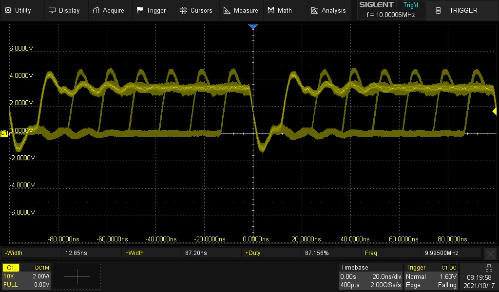
.
IhorNehrutsa commentedon Oct 17, 2021
Note 1) Not all frequencies can be generated with absolute accuracy due to
the discrete nature of the computing hardware. Typically the PWM frequency
is obtained by dividing some integer base frequency by an integer divider.
For example, if the base frequency is 80MHz and the required PWM frequency is
300kHz the divider must be a non-integer number 80000000 / 300000 = 266.67!
In fact, after truncating, the divider is set to 266, and the PWM frequency
will be 80000000 / 266 = 300751.9 Hz, but not 300kHz.
If the divider is set to 267(rounding), then the PWM frequency
will be 80000000 / 267 = 299625.5 Hz, but again not 300kHz.
ISP-IDF uses 80MHz LEDC_APB_CLK.
ISP-IDF does'n round the divider!!!
robert-hh commentedon Oct 17, 2021
That's my saying all along the line. In addition, the base crystal may not be precise as well. Typical tolerances range for 10 to 30 ppm. And I do not expect that the low cost modules go for the best (and more expensive) crystals/oscillators.
kdschlosser commentedon Oct 17, 2021
and you couple the divider not being fractional with only having microsecond timing precision and you don't get a perfect duty cycle along with not having a perfect frequency.
I think we are all on the same page with this.
@robert-hh, how are you managing to get over 4v of pwm output from the esp32??
robert-hh commentedon Oct 17, 2021
That's just the ringing of the probe and is not generated by the ESP32. For a quick hookup I use a standard 10MOhm probe with a long tip (3cm) and a long GND clip (12cm). The capacity of the tip and the inductivity of the GND wire form a LC oscillator, which is ping'ed by the fast transition of the ESP32 output. That increases also the displayed rise/fall times. If I use a different tip on the probe (GND, Tip < 1cm) or a different probe, the overshoot much smaller and the rise/fall times decrease.
But the standard probe is easy to handle, and if you know the errors, it's fine.
kdschlosser commentedon Oct 17, 2021
OK. that makes sense.
I don't know the PWM specification at all. The code I wrote for the Arduino simply measures the top duration and the bottom duration adds them together divides them my 1000000 to get seconds and I divide 1 by that number to get the frequency. the duty I am dividing the off duration by the sum of the on and off and multiplying it by 100 to get the %. The duty is how much on/off time there is in comparison to the total duration of the on and off. so the higher the resolution the smaller the changes in the on and off would be.
So the reason why the resolution lowers as the frequency increases is because the on + off decreases as the frequency increases and the ESP32 is unable to measure the time. So as the duty resolution decreases the on/off pulses increase to fill the space allotted by the frequency.
This is how I believe it works. I would have to read the specification to be sure, or you can tell me yes or no.
The frequency is measured by timing how ling it takes to get from the first arrow to the second.
The duty is the timing from the on period divided by the time measurement above.
The ESP has to decrease the resolution at higher frequencies because the duration of the on + off gets smaller as the frequency increases. So if the duty resolution stayed the same the ESP would have to be able to measure the duration with a much higher precision then it is able to. so to over come that problem it shrinks the resolution there for making the periods larger.
robert-hh commentedon Oct 17, 2021
The ESP like other devices to not measure anything. The simple model of a PWM module consist of a counter with a fixed input frequency F (e.g. 80MHz). The counter has a variable period N and a switch value S, with 0 <= S <=N. The counter starts at N = 0, setting the output value to 1. It it reaches S, it sets the output to 0. If it reaches N, it starts over. So the frequency of the output is F // N (using // for the integer division). The duty rate is S / N.
The ESP has a 16 bit counter for N, giving 65535 as largest value. With 80Mhz, the lowest frequency is ~1220.5 Hz, with a granularity of 65536 for the duty rate. If you want to have a frequency of 100kHz, you have to set N to 800, resulting in a granularity for the duty rate of 800. With 801 as N, you get ~99.875 kHz, with 799, you get 100.125kHz. For 10MHz, N has to be 8, and you end up with 8 possible different duty rate settings.
That's the basic operation. The ESP32 has a few extensions to that scheme. It can change F to F' = F // P (P = prescaler, range 1..256) as well so it can go to lower frequencies than 1220.5 Hz. The counter can count up and down, extending the range further by two, and more. I did not look into the sources how the ESP firmware determines N and P, which define the frequency precision. A simple attempt would just make N as large as possible for the best duty rate granularity. If the objective is best frequency match, it could try to find a value pair for N * P, such that F // ( N*P) matches best the target frequency.
kdschlosser commentedon Oct 17, 2021
it actually has a 20 bit counter for N.
The ESP32 determines what the resolution is by both an internal check and also by when gets set by the user. so if you have a 50Hz PWM you can set the duty resolution to any number of bits from 1 to 20. allowing and adjustable amount of duty. it's not "hard coded". I updated the PWM portion of the MicroPython code so it allows a user to adjust the duty resolution when the instance is constructed and also when the frequency is changed. and I added a function that returns the maximum amount of duty that can be set for the given frequency or bit depth which ever one has the lowest duty resolution.
https://docs.espressif.com/projects/esp-idf/en/latest/esp32/api-reference/peripherals/ledc.html#_CPPv416ledc_timer_bit_t
https://docs.espressif.com/projects/esp-idf/en/latest/esp32/api-reference/peripherals/ledc.html#_CPPv4N19ledc_timer_config_t15duty_resolutionE
kdschlosser commentedon Oct 17, 2021
measure is the wrong term. all it does is count, it is up to the user to know what the crystal frequency is which is what determine the length of time. so at 80Mhz the crystal provides approx 80 million pulses a second. the prescalar tells the ESP to count every X pulse. This brings the 80 million down into a manageable area to be able to produce the on/off times that are needed.
wangshujun-tj commentedon Oct 18, 2021
The LEDC module of esp32 is different from the PWM generated by common timers
Its cycle value can only use the integer power of 2, rather than using any end point (ARR) like common timers. The PWM cycle of esp32 is obtained based on an 10+8 bit prescaler, so only a small number of frequencies are accurate. Moreover, the frequency divider still uses decimal frequency division, which will show periodic jitter
In esp32, the hardware more suitable for generating PWM is the mcpwm module. The behavior of this module is very close to the common timer implementation. However, the absence of this hardware in C3 and S2 versions will lead to too large differences between versions.
Another suitable module is RMT, but there are too few channels available in the C3 version
robert-hh commentedon Oct 18, 2021
OK, I assumed the for PWM the mcpwm module was used. The LEDC module is different, with the 10+8 bit fractional prescaler and the 20 bit counter. Given that, the result should be more precise than it actually seems.
IhorNehrutsa commentedon Oct 19, 2021
See the latest commits of #7907
Please report bugs to #7907
IhorNehrutsa commentedon Jan 14, 2022
@kdschlosser @dpgeorge please close
Merge pull request micropython#7806 from dhalbert/no-report-id-out-re…